Full da Vinci
Table of Contents generated with DocToc
Acronyms used in this page are defined in Frequently Asked Questions.
There are two different groups of users for the dVRK mechatronics and software, those with a da Vinci Research Kit provided by Intuitive Surgical (2 MTMs, 2PSMs, stereo display and foot pedals) and those with a full decommissioned da Vinci system. This page addresses some issues specific to the later group.
It is important to notice that there are a few hardware features from the full da Vinci system that are not currently supported by the dVRK mechatronics and software:
- Video pipeline and messages in stereo display
- Audio pipeline
- Control panel and switches on the master console arm rest (on/off, scaling, arm pairing, ...)
- Height adjustment for the stereo display
- ...
On the other hand, the dVRK mechatronics and software support the camera manipulator (ECM) and will soon support the setup joints:
- For the ECM, we use a FPGA-QLA based PSM controller with a special configuration (XML file) to support the brakes.
- For the setup joints, we use a single FPGA-QLA board connected to a board designed by Intuitive Surgical (dSIB) which can interface with all 4 setup joints. This board has been designed and is being tested at JHU.
You can also access the head sensor and control the endoscope focus using custom cables. For more details regarding the cables (that you will need to assemble), see:
- Head sensor: head sensor options (see daVinci Head Sensor section)
- Camera focus: endoscope focus section on this page
You will be able to switch back and forth between the mechatronics from ISI and the dVRK controllers but this requires to unplug and replug a few cables. The user has to connect the arms, setup joints and foot pedal directly to the dVRK controllers:
- MTM cables can be found on the back of the master console, grey plastic covers need to be removed.

- Foot pedal cable can be found on the front of the master console, under the stereo display and the cover needs to be removed. Unplug the bottom part and connect it to the dVRK controller. This cable is rather short so one might consider investing in an extension cable (e.g. https://smile.amazon.com/Monoprice-6ft-DB15-Molded-Cable/dp/B002LWJ7TA).

- On the patient side, both setup joints and arms need to be unplugged from the back of the cart to be connected to the dVRK controllers. The long cables normally used to connect the patient cart to the master console are not used. The cables coming from the arms shouldn't be connected to the back to the cart, they must be connected directly to the dVRK controllers! Since the cables coming from the arms are not very long, you will need to place all the PSM and ECM controllers really close behind the patient cart.

Make sure you use an ECM controller, i.e. a controller with a single 36V motor power supply for both FPGA-QLA sets. Controllers for the MTMs have two power supplies for the motors, a 24V for the first 4 axis and a 12V for the last 4 axis. Controllers for the PSMs have a single power supply for all axis but it is only 24V. On your controller, set the board IDs to 4 and 5 (see XML configuration). As for the PSMs, you must connect the cable that comes directly from the arm to the controller.
A default configuration file can be generated by our Matlab config generator. You'll need the ECM calibration file (.cal) and make sure you select "ECM" for the hardware type (see XML configuration). A typical ECM .cal file looks like this:
FileType      = [ 'ECM_CAL' ]
FileVersion   = [ 305 ]
serial_number = [ 29738 ]
part_number   = [ 380189 ]
part_version  = [ 2 ]
date          = [ '02-Dec-2010 12:35:09' ]
iteration     = [ 4 ]
cal_version   = [ 40201 ]
id            = [ 3500 ]
style         = [ 3523 ]
type          = [ 0 ]
comment       = [ 'ECM_STYLE_COFFEE_ROSCOE_CURVED_LONG_CABLE' ]
joint.signal_range(UPPER_LIMIT,1:ECM_JNT_POS_GR_DOFS) = [ 1.604483 1.159451 0.256325 1.564778 ]
joint.signal_range(LOWER_LIMIT,1:ECM_JNT_POS_GR_DOFS) = [ -1.563787 -0.776968 -0.003793 -1.566741 ]
motor.pot_input_gain(1:ECM_MOT_DOFS)                  = [ 0.001136 0.000737 -0.000153 -0.000871 ]
motor.pot_input_offset(1:ECM_MOT_DOFS)                = [ -2.294867 -1.308188 0.439879 1.782719 ]
motor.pot_limit_checks(UPPER_LIMIT,1:ECM_MOT_DOFS)    = [ 3990.000000 3868.000000 3245.000000 4096.000000 ]
motor.pot_limit_checks(LOWER_LIMIT,1:ECM_MOT_DOFS)    = [ 87.000000 196.000000 854.000000 0.000000 ]
Don't use this specific .cal file snippet. You might have to fix the .cal file for the following issues:
- Some strings might be missing some single quotes, e.g.
ECM_CAL - The size of arrays might be wrong, i.e. the dVRK config generator expects 4 values for all the arrays. If you happen to have more, keep the first 4 and remove all the others.
- The array ranges use the constants ``ECM_MOT_DOFS
andECM_JNT_POS_GR_DOFS` defined by the XML config generator.
In the generated configuration file, pay attention to the section "AnalogBrake"
    <AnalogBrake AxisID="0" BoardID="5">
        <AmpsToBits Offset="32819" Scale="5242.88"/>
        <BitsToFeedbackAmps Offset="-6.25" Scale="0.000190738"/>
        <MaxCurrent Unit="A" Value="0.300"/>
        <ReleaseCurrent Unit="A" Value="0.300"/>
        <ReleaseTime Value="2.000"/>
        <ReleasedCurrent Unit="A" Value="0.080"/>
        <EngagedCurrent Unit="A" Value="0.000"/>
    </AnalogBrake>
There are 4 important values that will need to be tweaked to your hardware:
-
ReleaseCurrent: current required to release the brakes - the "Unit" field in the XML file is not read by the software, replacing it bymAwon't have any effect so make sure the specify theValuein amperes. -
ReleaseTime: amount of time you need to keep the current high to release the brakes (in seconds). -
ReleasedCurrent: current required to maintain the brakes released. This value should be significantly lower than the current to initially release the brakes. -
EngagedCurrent: current required to engage (lock) the brakes. On the ECM, always zero.
Please note that the values provided on this page are hardware specific and you must adjust them to your system. Ideally, you want to find the lowest possible current that still work reliably on your hardware, see below.
Current calibration needs to be performed for both the actuators and the brakes. Once you have generated the ECM XML configuration files, follow instructions from Calibration. The main difference for the ECM is that you need to follow the procedure twice, once without the -b option and once with the -b option. Overall, the process is:
-
sawRobotIO1394CurrentCalibration -c file.xmlfor the initial motor current calibration -
sawRobotIO1394CurrentCalibration -c file.xml-newto verify motor current calibration -
sawRobotIO1394CurrentCalibration -b -c file.xml-new-newfor the initial brake current calibration -
sawRobotIO1394CurrentCalibration -b -c file.xml-new-new-newto verify brake current calibration -
mv file.xml-new-new-new-new file.xmlto save the fully calibrated file
This is a VERY IMPORTANT PROCEDURE. At that point, we don't have a utility program the automatically adjust the parameters specific to the brakes, namely the 4 following values in the XML file:
-
ReleaseCurrentandReleaseTime ReleasedCurrent-
EngagedCurrent, though this one is easy, it should be set to 0.
For this procedure we will use the sawRobotIO1394QtConsole program along with the ECM XML configuration file for your arm. You will need to manually edit the XML file and between changes, test using the sawRobotIO1394QtConsole program.

-
The first step is to determine the
ReleaseCurrent.- In the XML file, set all the
ReleasedCurrent(NOTE: releaseD current) to zero and theReleaseTimeto 60 seconds. Start from a low value for the 3ReleaseCurrentvalues (~0.1 for 100 mA). - Start the
sawRobotIO1394QtConsoleandEnable Allto power the actuators and brakes. - Press the
Releasebutton for the brakes. You should see the requested current move to the value set in the XML file and a current feedback close to it. After 60 seconds (or whateverReleaseTimeyou've set in the XML file), current should go back toReleasedCurrentvalue (i.e. 0 for now). - During these 60 seconds, try to move the ECM, joint by joint. If you stand close to the arm, you should even hear a click if the brakes get released.
- If a given brake is not released, quit the application, increase the value of
ReleaseCurrent(andMaximumCurrent) for the corresponding joint in the XML file and try again. - You can increase the requested current to an extent, i.e. the hardware is limited by the power supply so make sure you always check the current feedback. If the current feedback doesn't increase as you're increasing the requested current (and software maximum current), it means that you have reach the maximum possible with your power supply.
- In the XML file, set all the
-
Once you've found the proper values for
ReleaseCurrent, you can decrease theReleaseTimevalue to 2.0. -
The last step is to find the lowest possible for
ReleasedCurrent. This is the current appliedReleaseTimeseconds afterReleaseCurrentto keep the brakes from re-engaging. It's IMPORTANT to find the lowest possible value. Again, start from a low value and increase progressively until you find settings such that the brakes stay released.
We are not totally sure how much variability there is between systems. In order to get a sense for it, please update the following table after you calibrated your brakes:
| System | 1 Release (A) | 1 Release (s) | 1 Released (A) | 2 Release(A) | 2 Release (s) | 2 Released (A) | 3 Release(A) | 3 Release (s) | 3 Released (A) |
|---|---|---|---|---|---|---|---|---|---|
| JHU | 0.250 | 2.0 | 0.090 | 0.220 | 2.0 | 0.090 | 1.100 | 2.0 | 0.200 |
| ISI | 0.250 | 2.0 | 0.100 | 0.210 | 2.0 | 0.100 | 1.200 | 2.0 | 0.200 |
| WSU | 0.270 | 0.5 | 0.120 | 0.300 | 0.5 | 0.130 | 1.100 | 2.0 | 0.170 |
| UCL | 0.250 | 2.0 | 0.040 | 0.140 | 2.0 | 0.040 | 1.100 | 2.0 | 0.200 |
Important note for older dVRK controllers: We found that the power requirements are close to the maximum amount of power a 24V power supply can deliver. There is some variability between different systems and brakes so you might need to upgrade the power supply to 36V in the controller enclosure. To check if you have reached the maximum deliverable power, keep an eye on the current feedback. These values should be close to the required current. If the current feedback seems to plateau while you increase the requested current, you'll likely need to upgrade your power supply.
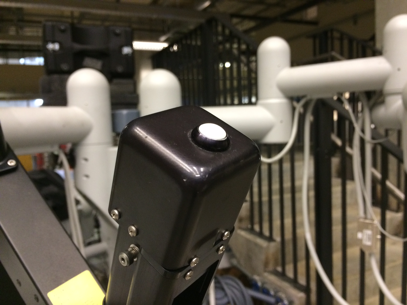
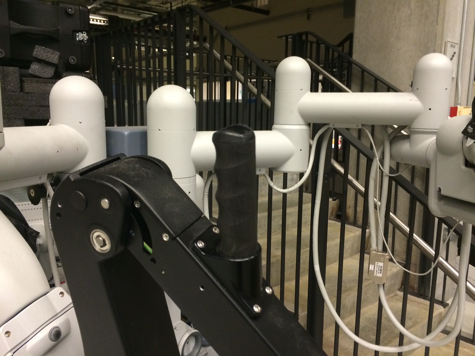
The setup joint switch/button on the ECM is not using the same digital input as the setup joint switch on the PSMs. This was unfortunately discovered after the dMIB were designed (pre 2015 revisions). In other words, you need to hack the dMIB to short a couple pins. You will need someone in house who can do some soldering.
Using the sawRobotIO1394QtConsole you should be able to monitor the switch events, i.e. press and release the different buttons on the ECM arm for a little bit and monitor the changes in the "Buttons" widget/window.
-
Manipulator switch
-
SUJ switch
-
IO Widget

The Arm (aka manipulator) switch should work and the SUJ shouldn't until you hack the dMIB. To modify the dMIB, follow these instructions.
If you are absolutely sure the brakes are working (i.e. get released and stay released), you should be able to test the whole arm, including PIDs, homing, kinematics and manipulator clutch using the application sawIntuitiveResearchKitQtArm. The command lines syntax is:
sawIntuitiveResearchKitQtArm:
 -i <value>, --io <value> : configuration file for robot IO (see sawRobotIO1394) (required)
 -p <value>, --pid <value> : configuration file for PID controller (see sawControllers, mtsPID) (required)
 -k <value>, --kinematic <value> : configuration file for kinematic (see cisstRobot, robManipulator) (required)
 -n <value>, --arm-name <value> : arm name, i.e. PSM1, ... as found in sawRobotIO configuration file (required)
 -f <value>, --firewire <value> : firewire port number(s) (optional)
 -g <value>, --gcmip <value> : global component manager IP address (optional)
For the --arm-name or -n option, use the string ECM. For the -k option, use the file dvecm.rob. For the -p option, use the file sawControllersPID-ECM.xml. For the -i option, make sure you use the sawRobotIO XML file you generated for your system.
Once the application is started, hit the home button. The ECM should power properly, release the brakes and go to the zero position. You can then use the different widgets to make sure everything properly. You can press the manipulator clutch button to move the arm manually.

TBD Hardware is not yet available for setup joints.
Joints diameters:
- PSM1:
- 0: Translation, where's the origin?
- 1: Rotation, vertical axis, diameter 147.5 mm (all -90/+90)
- 2: Rotation, vertical axis, diameter 133.5 mm (PSM1 -135/0, PSM2 0/+135, PSM3/ECM -90/+90)
- 3: Rotation, vertical axis, diameter 107.5 mm (all -90/+90)
- 4: Rotation, horizontal axis, diameter 93.3 mm (PSMs only -135/+135)
- 5: Rotation, "vertical" axis, diameter 89.4 mm (PSMs only -135/+135)
You can download a document to print on letter paper: dVRK labels for SUJ. The .svg file can be opened, modified and printed using inkscape on Linux. You can also find a pdf version if you don't have inkscape. Please, if you update the .svg file, make sure you also update the .pdf.
-
Focus controller
- Back of endoscope focus controller, male DSUB 15 pins
- Focus +, short pin 1 with pin 9, power comes from pin 1 (floating high, 5V)
- Focus -, short pin 4 with pin 9, power comes from pin 4 (floating high, 5V)
-
dVRK controller
- Using digital outs on first QLA FPGA
- Digital out 3 connected to DB 15 on
DOF 1:- Pin 14: on: 0V, off: 5V. We should use this pin for focus + control, off by default
- Pin 10 is grounded
- Digital out 2 connected to DB 15 on
DOF 2:- Pin 14: on: 0V, off: 5V. We should use this pin for focus - control, off by default
- Pin 10 is grounded
-
Cable wiring
- The cable is "Y" shaped, on the dVRK controller side you will need two male DB 15 connectors (3 rows of 5 pins) which will plug in the connector labeled
DOF 1andDOF 2on the back of the dVRK controller. On the ISI focus controller side, you need a single male DB 15 connector (1 row of 8 pins, 1 row of 7 pins). - You need 3 wires in your cable:
- Focus + signal: dMIB
DOF 1pin 14 <-> Focus controller pin 4 - Focus - signal: dMIB
DOF 2pin 14 <-> Focus controller pin 1 - Ground: dMIB
DOF 1pin 10 and/orDOF 2pin 10 <-> Focus controller pin 9 (dMIB share ground betweenDOF 1andDOF2)
- Focus + signal: dMIB
- The cable is "Y" shaped, on the dVRK controller side you will need two male DB 15 connectors (3 rows of 5 pins) which will plug in the connector labeled

Once you've build your cable, you can modify your console JSON configuration file and add:
    "endoscope-focus": {
        "io": "sawRobotIO1394-MTML-dv-endoscope-focus.xml"
    }
The example above assumes that:
- You're using the dVRK software rev 1.6 or above
- You have connected to the camera focus cable to the MTML controller. If you're connecting the endoscope focus unit to another controller and you can't find the corresponding configuration file in
sawIntuitiveResearchKit/share/io, feel free to create one and contribute it back to the community - You have the da Vinci foot pedal connected with the Camera +/- toggle pedal properly working. You can check in the Qt graphical user interface, under the IO/Buttons tab.
At that point, you should be able to control the camera focus using the foot pedals. When pressing the +/- pedal you should:
- See the focus change
- See the "Focus In"/"Focus Out" LED turn on/off on the vision cart
- Hear the motor on the camera head

Community
Getting Started
- First Steps
- Software installation
- Controller Connectivity
- Configuration files
- Hardware Setup
- Calibration
- Classic/Standard
- Si
- Examples
Advanced
- Software Architecture
- Application Development
- APIs
- UI Customization
- Teleoperation
- Kinematics Simulation
- Potentiometer Issues
- Development Branches
- Release Checklist
- Projects
- Controllers/versions
- E-STOP Wiring
- Full da Vinci System
- Head Sensor
- Foot Pedals
- Video
- Instruments
Miscellaneous
- Frequently Asked Questions
- User manuals Classic and Si moved
- QLA Heat Sink
- Build w/o ROS Linux Mac
- cisst
- JHU
Deprecated