Connection Based Routing
Routing is defined by a connection graph or a wiring diagram. Routeable devices are sources, midpoints, or destinations. Devices are connected by tie lines. Tie lines represent the cables connecting devices, and are of type audio, video or both. Routes are made by telling a destination to get an audio/video/combined route from a source.
Essentials routing is described by defining a graph of connections between devices in a system, typically in configuration. The audio, video and combination connections are like a wiring diagram. This graph is a collection of devices and tie lines, each tie line connecting a source device, source output port, destination device and destination input port. Tie lines are logically represented as a collection.
When routes are to be executed, Essentials will use this connection graph to decide on routes from source to destination. A method call is made on a destination, which says “destination, find a way for source xyz to get to you.” An algorithm analyzes the tie lines, instantly walking backwards from the destination, down every connection until it finds a complete path from the source. If a connected path is found, the algorithm then walks forward through all midpoints to the destination, executing switches as required until the full route is complete. The developer or configurer only needs to say “destination, get source xyz” and Essentials figures out how, regardless of what devices lie in between.
PepperDash.Essentials.Core.Routing.IRoutingSourcePepperDash.Essentials.Core.Routing.IRoutingOutputsPepperDash.Essentials.Core.Routing.IRoutingInputsPepperDash.Essentials.Core.Routing.IRoutingInputsOutputsPepperDash.Essentials.Core.Routing.IRoutingSinkNoSwitchingPepperDash.Essentials.Core.Routing.IRoutingSinkWithSwitching
The diagram below shows the connections in a simple presentation system, with a few variations in connection paths. Example routes will be described following the diagram.
Each visible line between ports on devices represents a tie line. A tie line connects an output port on one device to an input port on another device, for example: an HDMI port on a document camera to an HDMI input on a matrix switcher. A tie line may be audio, video or both. It is essentially a logical representation of a physical cable in a system. This diagram has 12 tie lines, and those tie lines are defined in the tieLines array in configuration.
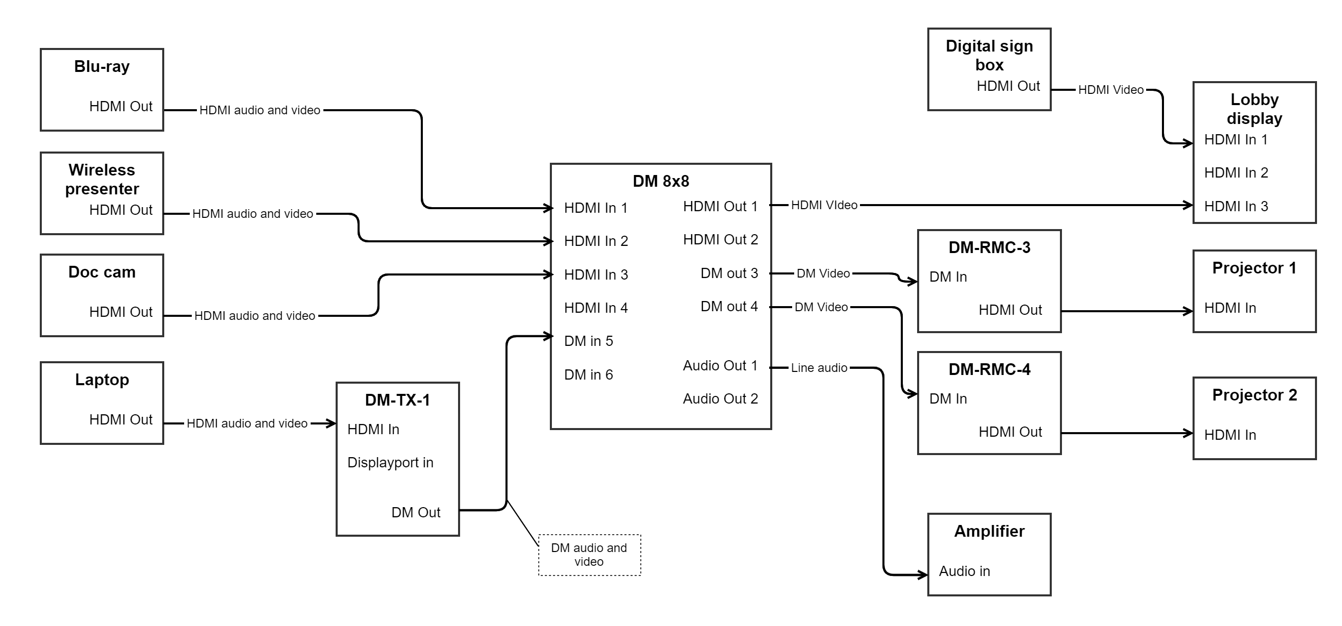
Let’s go through some examples of routing, using pseudo-code:
- Method call: “Projector 1, show Doc cam.” Routing will walk backwards through DM-RMC-3 and DM-8x8 iterating through all “wired up” ports until it finds a path back to the Doc cam. Routing will then step back through all devices in the discovered chain, switching routes on those that are switchable: Doc cam: no switching; DM 8x8: route input 3 to output 3; DM-RMC-3: no switching; Projector 1: Select input HDMI In. Route is complete.
- Method call: “Projector 2, show Laptop, video-only.” Routing will walk backwards through DM-RMC-4, DM 8x8, DM-TX-1, iterating through all connected ports until it finds a connection to the laptop. Routing then steps back through all devices, switching video where it can: Laptop: No switching; DM-TX-1: Select HDMI in; DM 8x8: Route input 5 to output 4; DM-RMC-4: No switching; Projector 2: Select HDMI input. Route is complete.
- Method call: “Amplifier, connect Laptop audio.” Again walking backwards to Laptop, as in #2 above. Switching will take place on DM-TX-1, DM 8x8, audio-only.
- Very simple call: “Lobby display, show signage controller.” Routing will walk back on HDMI input 1 and immediately find the signage controller. It then does a switch to HDMI 1 on the display.
All four of the above could be logically combined in a series of calls to define a possible “scene” in a room: Put Document camera on Projector 1, put Laptop on Projector 2 and the audio, put Signage on the Lobby display. They key takeaway is that the developer doesn’t need to define what is involved in making a certain route. The person configuring the system defines how it’s wired up, and the code only needs to tell a given destination to get a source, likely through configuration as well.
All of the above routes can be defined in source list routing tables, covered elsewhere (make link).
Ports are logical representations of the input and output ports on a device.
A source is a device at the beginning of a signal chain. For example, a set-top box, or a camera. Source devices typically have only output ports.
Source devices in Essentials must implement IRoutingOutputs or IRoutingSource
A midpoint is a device in the middle of the signal chain. Typically a switcher, matrix or otherwise. Examples: DM chassis; DM-TX; DM-RMC; A video codec. These devices will have input and output ports.
Midpoint devices must implement IRoutingInputsOutputs. Midpoints with switching must implement IRouting.
A sink is a device at the end of a full signal path. For example, a display, amplifier, encoder, etc. Sinks typically contain only input ports. They may or may not have switching, like a display with several inputs. Classes defining sink devices must implement IRoutingSinkNoSwitching or IRoutingSinkWithSwitching.
A tie-line is a logical representation of a physical cable connection between two devices. It has five properties that define how the tie-line connects two devices. A configuration snippet for a single tie line connecting HDMI output 1 on a Cisco RoomKit to HDMI input 1 on a display, carrying both audio and video, is shown below.
{
  "sourceKey": "ciscoSparkPlusCodec-1",
  "sourcePort": "HdmiOut1",
  "destinationKey": "display-1",
  "destinationPort": "HdmiIn1",
  "type": "audioVideo"
}Todo: Define Interfaces IRouting, IRoutingOutputs, IRoutingInputs